Description
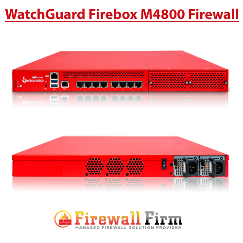
WatchGuard Firebox M4800 Firewall
Firebox M4800 Hardware Guide
WatchGuard security appliances deliver unparalleled unified threat management, superior performance, ease of use, and value. Powerful subscription-based security services deliver in-depth defenses against advanced malware, ransomware, botnets, trojans, viruses, drive-by downloads, phishing and much more.
This guide introduces the Firebox M4800, a RoHS-compliant (lead-free) hardware product offered by WatchGuard. The Firebox M4800 consolidates critical network and security functions into a single, centrally managed device, and is ideal as the ‘hub’ for distributed, hub-and-spoke type deployment scenarios.
Fireware OS
The Firebox M4800 device uses WatchGuard’s next generation UTM OS — Fireware OS. Each Firebox M4800 device includes Fireware OS and delivers exceptional protection against today’s sophisticated threats to make sure that your business stays connected. For more information on the features of Fireware OS,
About Your Hardware
Hardware Specifications
This table shows the hardware specifications for the WatchGuard Firebox M4800.
| Processor | Intel Coffee Lake Xeon E-2176G |
| Storage | 256 GB Solid State HDD |
| Memory: DDR4 | 16 GB |
| Power Supply | Dual power supplies 300W 100-240VAC/5-3A/50-60Hz |
| Dimensions | D = 46.8 cm (18.42″) W = 43.1 cm (16.96″) H = 4.4 cm (1.73″) |
| Weight | 8 kg (17.63 lbs) |
Interface Specifications
This table shows the interface specifications for the WatchGuard M4800 as shipped.
| Management Interface | 1x 1000 Base TX (10/100/1000Mbps), RJ45 connector |
| Network Interfaces | 8x 1000 Base TX (10/100/1000Mbps), RJ45 connector |
| I/O Interfaces | 2 USB 3.0 1 RJ45 RS232 console port |
The Firebox also has two slots where you can install additional interface modules. The supported interface modules are described in the Hardware Description section.
Environmental Requirements
To safely install your Firebox, we recommend that you:
- Install it in a network rack.
- Put it in a secure area, such as a locked room, to block the device from people who do not have permission to use it.
- Connect it to a conditioned power supply to prevent damage from sudden power changes.
This table shows other environmental requirements for the M4800 appliance.
| Operating Temperature | 0° to 40°C (32° to 104°F) |
| Operating Humidity | 5% to 90% non-condensing |
| Non-operating Temperature | –10° to 70°C (14° to 158°F) |
| Non-operating Humidity | 5% to 90%, non-condensing |
Hardware Description
Buttons and Indicators
Power
The power indicator is green when the device is powered on.
Arm/Disarm
When the device is armed and ready to pass traffic, this indicator is green. When the device is powered on, but not ready to pass traffic, this indicator is red.
Storage
When there is activity on the internal storage, this indicator is yellow.
Power Button
The Power button is lit to indicate power status. It is green when the Firebox is powered on, and red when power is available, but the Firebox is powered off.
When the Power button is red, press it to power on the Firebox.
When the Power button is green, press and hold the power button for five seconds to power off the Firebox. The Firebox does not power off if you briefly press the Power button.
Reset Button
The Reset button, located to the left of the USB interfaces, resets the device to factory-default settings. To reset the device,
Built-in Interfaces
The Firebox M4800 has eight built-in network interfaces, a management interface, two USB interfaces, and one serial console port.
Dual USB interfaces
The device includes two USB interfaces. Connect a USB storage device for USB backup and restore, or to store a support snapshot. For more information,
Console port
An RJ45 connector for the serial (console) interface is located above the USB interfaces. You can connect to this serial interface to log in to the Fireware Command Line Interface.
For more information about the command line interface, see the current Command Line Interface Reference available on the Firebox documentation page at
Management interface
The management interface, labeled or Mgmt, is located to the right of the USB interfaces. You must connect to this interface to configure the Firebox when it starts with factory-default settings. The management interface is interface 24.
RJ45 Ethernet interfaces
Interfaces 0 – 7 are RJ45 Ethernet interfaces that support link speeds of 10, 100, or 1000 Mbps. Each RJ45 interface has two indicators. The right indicator shows the interface connection status. The left indicator shows interface activity.
| Indicator | Indicator Color | Interface Status |
|---|---|---|
| Connection (right) | Yellow | Link at 1000 Mbps |
| Green | Link at 100 Mbps | |
| Not Lit | Link at 10 Mbps or no link | |
| Activity (left) | Yellow, blinks | Power on, network activity |
| Not Lit | Power off, no connections |
Interface Modules
To add more interfaces to your Firebox, you can install an interface module in an available interface module slot. You must install the interface module before you can configure the interfaces. For instructions to install or remove interface modules,
Interface modules are not hot-swappable. To avoid damage to the system, power off the Firebox before you install or remove interface modules.
You can purchase these compatible interface modules from an authorized WatchGuard reseller:
- WatchGuard Firebox M 8 Port 1 Gb Copper Module — WatchGuard SKU WG8592
- WatchGuard Firebox M 8 Port SFP Fiber Module — WatchGuard SKU WG8593
- WatchGuard Firebox M 4 Port 10 Gb SFP+ Fiber Module — WatchGuard SKU WG8594
- WatchGuard Firebox M 2 Port 40 Gb QSFP+ Fiber Module — WatchGuard SKU WG8023
For each interface module, ports are numbered from 0-7, 0-3, or 0-1. The interface numbers that appear in the Firebox configuration depend on the number of ports on the interface module, and the interface module slot where the interface module is installed.
| Installed in slot | Number of Ports | Modular Interface Port Numbers | Interface Numbers in Management Software |
|---|---|---|---|
| A | 8 | A0-A7 | 8-15 |
| 4 | A0-A3 | 8-11 | |
| 2 | A0-A1 | 8-9 | |
| B | 8 | B0-B7 | 16-23 |
| 4 | B0-B3 | 16-19 | |
| 2 | B0-B1 | 16-17 |